Shape Memory Alloys Achieve High Force and Precision
Shape Memory Alloy based linear actuators have the potential to serve numerous applications that call for high force, low weight, and/or high precision.
With very little fanfare a special class of alloys has been finding its way into our daily lives. From indestructible eyewear to smartphone cameras to coronary stents, this material is being used in a diverse range of applications. We are talking, of course, about shape memory alloys (SMAs). From simple beginnings in a naval ordnance lab, the commercial and scientific uses of this material are numerous yet many engineers and designer remain unsure of how to utilize it. Here we explore the use of SMA in an electric linear actuator. With an understanding of the actuators construction, operating principals, and capabilities the suitability of SMAs for a particular application can be considered.
When the Shape Memory Alloys material is formed into a wire, this shape-change is realized as a shortening, or induced strain, of the wire by as much as seven percent of its total length.
Fundamental Concepts
The most widely used Shape Memory Alloys are comprised of a roughly 50/50 molar mix of nickel and titanium. This alloys popularity is due to several factors; important in this discussion is the material’s ability to alter its physical shape when heated above ambient temperature. Having a shape transition temperature above ambient is key as it permits the application of energy to effect the shape-change, and the process will reverse when the energy source is removed and heat is rejected into the surrounding environment.
When the SMA material is formed into a wire, this shape-change is realized as a shortening, or induced strain, of the wire by as much as seven percent of its total length. Coupled with the wire’s inherent ability to repeatedly self-generate and recover from stresses in excess of 250 MPa, this makes the material a prime candidate for driving linear actuators.
While the application of SMA for small displacements and forces is possible, this article considers the opposite end of the spectrum: What are the practical upper limits of SMA wire-based force and displacement? The maximum diameter of commercially available SMA wire is 0.5 mm (0.020 in.), which is capable of generating pull forces in excess of 30 N (7 lbf). While some applications may fall under this force threshold, the capabilities of an SMA-based actuator are greatly expanded when multiple strands of SMA wire are employed in parallel. By way of example, if an application calls for 300 N of force, ten wire segments of 0.5 mm diameter can be used to generate that force, provided they all work in unison.
Shape Memory Alloys Benefits | For applications that require fast, repetitive cycles, a liquid medium with a relatively high heat capacity and thermal conductivity provides a quick return rate.
The challenge of having multiple SMA wires work in unison is that the temperature of each strand of wire must be in lockstep with each other. If one strand is heated faster than the others it contracts sooner and, as a result, is susceptible to pulling more than its allotted share of load. This creates uneven pulling and overstressing of wires. Compounding this issue is the general requirement to evenly heat the entire length of each wire segment such that its full potential to contract is achieved. Approaching this uniform heating challenge using traditional conductive, convective, or radiative heat transfer means is highly difficult and impractical. However, the problem can be solved through the application of Joule heating.
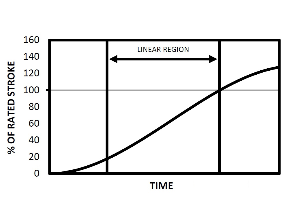
As with any metal, Shape Memory Alloys conduct electricity; in wire form, the material presents a nominal resistance per unit length. When connected to a voltage source, current flows through the wire, which then undergoes Joule heating. Over time this heat drives the SMA wire temperature up uniformly along its length. As the wire approaches, and then reaches, its transition temperature, the continued application of current can then be harnessed to perform useful work. When Joule heating is applied to specially trained and heat-treated SMA wire, a highly linear relationship between the wire’s length and energy input is obtained, as illustrated in figure 1.
Once Joule heating has begun, the wire will begin to reject heat to its surroundings. For applications that require the actuator to hold position, the voltage source can be modulated such that the power input matches the heat dissipation. When the voltage source is removed, heat rejection will cause the wire temperature to drop and approach ambient conditions. The rate of heat rejection is entirely dependent on the physical environment surrounding the wire. When suspended in a fluid, convective heat transfer is the dominant mode of heat transfer. Fluid selection is a critical consideration as it dictates the power consumption and cycle rate of the actuator. For applications that require holding at a precise position for long durations, power consumption can be reduced by using a gas medium. For applications that require fast, repetitive cycles, a liquid medium with a relatively high heat capacity and thermal conductivity provides a quick return rate.
While heat rejection is needed to cause the SMA wire to return to its original length, it is not the only driving factor: A return force must be applied to extend the wires back to their original length. This return force does, in fact, dictate the amount of available wire strain for the subsequent cycle. The higher the return force, the greater the potential for Joule heating-induced strain, and the higher the return rate of the actuator. For applications where sufficient return force is not present, the actuator design must incorporate a return biasing feature. This biasing feature can come in many forms, including a simple return spring. A bias spring in the actuator introduces a trade-off between available force and travel: While a heavier return spring will increase the available travel it will reduce the actuator’s ability to generate useful force.
Enhanced Actuator Design
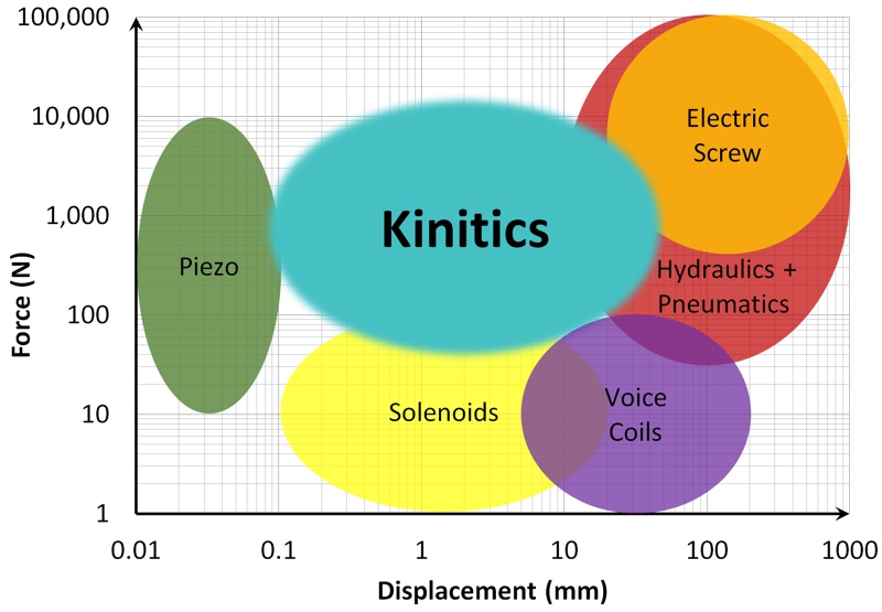
By arranging parallel SMA wire strands into a bundle and applying Joule heating to achieve uniform temperature control, the foundation for a new class of electric actuator is laid; these actuators have the force and displacement capabilities shown in figure 2.
An instantly recognizable form factor for such an actuator is that of a moving rod supported inside a cylinder body. An example of a commercial SMA-based actuator is shown in figure 3. Extending the rod out one end of the cylinder body or the other end provides a simple attachment point that provides either a pushing or pulling force. With this underlying understanding of construction and actuation we can now begin to explore the unique characteristics of an Shape Memory Alloys -based actuator. In the configuration shown, there is no rotating, slipping, or sliding element in play and, as such, there is an inherent lack of backlash or mechanical slop in the connected system. In every sense of the term an SMA-based linear actuator produces direct linear motion.

Another defining aspect of a SMA-based actuator is its relatively high force-to-weight ratio. Take, for example, an application that requires 500 N of force and 5 mm of travel. Assuming a standard biasing spring is used, a meager 6 g [0.2 oz] of wire is sufficient to satisfy the application. By way of comparison, a solenoid would require between two and three orders of magnitude more mass to generate this force and displacement. In practice the design of the actuator body and rod tends to be the major contributing factor to total weight.
From an electrical standpoint a SMA-based actuator behaves as a purely resistive load. By bundling multiple strands together it is possible to tailor the total resistance of the load to suit the available power supply and desired response time. For DC applications between 6 and 50 volts, a resistive load from sub-ohm to several ohms can be configured. For standard 120 VAC applications a resistive load from several ohms to upwards of 100 ohms can be used.
Through experimentation and application trials, SMA-based actuators have demonstrated exceptional positional accuracy and precision.
When operated in its linear region the actuator responds to modulating power in a smooth and highly predictable manner. Because the actuator acts as a resistive load, complex communication or control techniques are generally not needed; in most cases a simple PI control loop can be applied. When controlled using pulse width modulation, a low sub-kilohertz frequency can maintain repeatable accuracy and precision to within 5 µm (0.0002 in.).
Figure 4 illustrates an example of a SMA-based actuator, powered by 120VAC and connected to a 725 N (163 lb·f) load, responding to three positional step changes. While position feedback is the most obvious telemetry to apply in a closed loop system, the SMA-based actuators also respond well to control systems that utilize force feedback..
SMA-based linear actuators have the potential to serve numerous applications that call for high force, low weight, and/or high precision.
Summary
By bundling Shape Memory Alloys wire into a multi-strand design it is possible to enhance the shape memory benefits of the wire. SMA-based linear actuators have the potential to serve numerous applications that call for high force, low weight, and/or high precision. The actuators can be connected to industry-standard DC and AC power supplies and should be considered for any applications requiring between 1 mm and 10 mm of travel.
This article was written by Dean Pick, President of Kinitics Automation Limited and was originally published in Tech Briefs magazine.
Reprinted with permission from Tech Briefs, Vol. 42, No. 6.
